What you have there are the 12 available latches to hold your payload inside the PLB. You should only need 5: 2 starboard (top line), 1 keel (center line) and 2 port (bottom line).
The orbiter attachment should be in the keel, so the keel attachment should have the "Attachment" checkbox marked.
Then you have the "Latch Connection" combo boxes, which will allow you to connect the latches to the switches on panel A6U, so you can unlatch them to release your payload. There are a total of 15 available connections, but you only need 5 as your payload only has 5 latches, so pick them as you please.
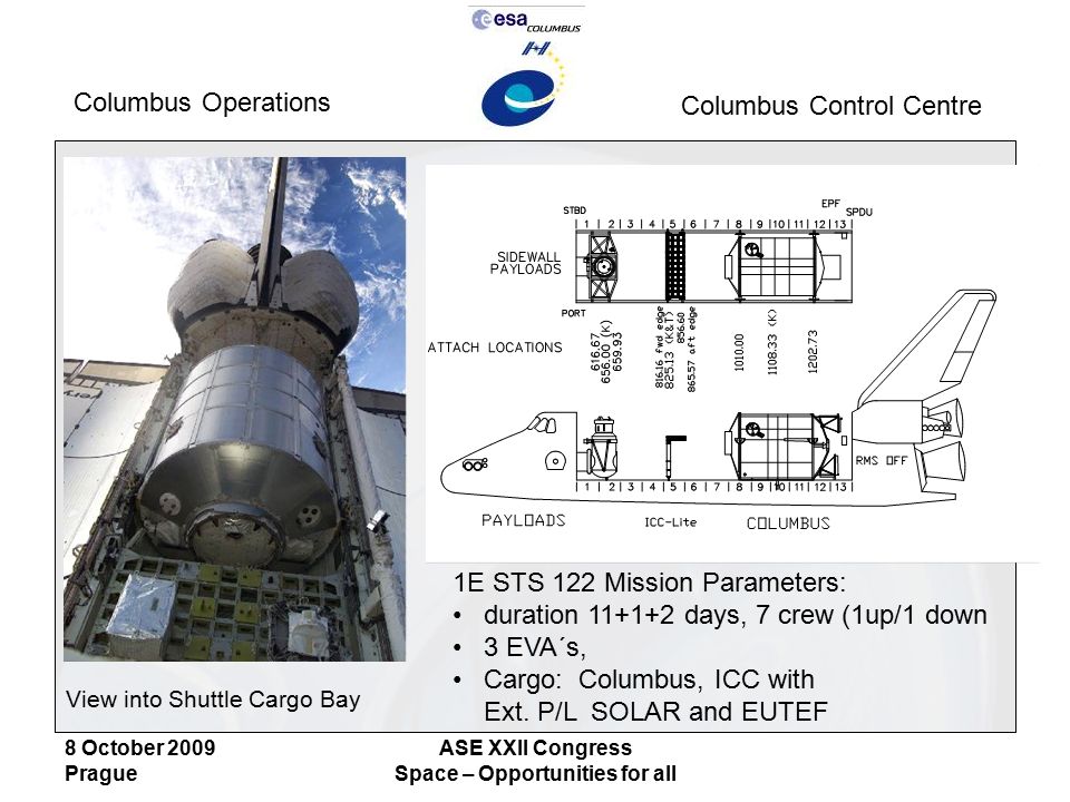
Now the big one: the PLIDs, which dictate where the payload attaches. The payload should have trunnions to be held by the latches, and the latches can only be at certain locations in the PLB, which are identified by their PLID number. They start at 155 (don't know why) and go up as you move aft in the PLB. If you have a diagram like this:
you can find out the PLIDs used* (see links below), otherwise you will have to go trial-and-error or find a really good photo and count the slots where the latches mount.
The latches can be "reversed", placing the "fat" latch motors on the other side, allowing a bit more space for some PLB structures or another latch.
Finally, you may want the latches to have guides to help with removing or replacing the payload in the latches.
Some posts with info:
https://www.orbiter-forum.com/threads/space-shuttle-vessel.37856/post-599599
https://www.orbiter-forum.com/threads/space-shuttle-vessel.37856/post-599720
*) I might add the Xo locations next to the PLID to make it easier to use these diagrams.