SDK Question About Touchdown Vertexes and "convex hulls" (again)

So I apply hover and got her above the surface and the correct orientation. And cut the hover and let her drop. She landed correctly but then reverted to under the surface

I wrote that a couple of years ago, I think I had a reason to do so, what you describe is similar to the problem I had. In fact I was working on the robotic Chinese lander which has 4 legs like yours :

And I found out that you have to define those points counterclockwise, else the vessel starts "inverted". I think it is a consequence of Orbiter being "left-handed". So to be consistent I'm redefining all points in that counterclockwise logic.
 
The order of the first three touchdown points tells orbiter which way of the vessel is up in landed state. Orbiter will load the vessel with the scenario and, if it is in landed state, will try to put it in the right place, the right way up.
I'm not sure how the order was again, I think it's documented in the API docs. I'm not even sure your order is wrong, but that's the first thing I'd check. I'm surprised I still know as much about it as I do after this long time...
 
  • Like
Reactions: GLS
Thanks. Now I get this. Now the 2 left gear are above and 2 right are sunk. But sure how accurate it is to make the all 4 on the ground.
static const DWORD ntdvtx_geardown = 5;
static TOUCHDOWNVTX tdvtx_geardown[ntdvtx_geardown] = {
{_V(3.4641, -4.1609, 3.452), 70007.4, 49275.1, 3, .2},
{ _V(-3.4641, -4.1609, 3.452), 70007.4, 49275.1, 3, .2},
{_V(-3.4641, -4.1609, -3.452), 70007.4, 49275.1, 3, .2},
{ _V(3.4641, -4.1609, -3.452), 70007.4, 49275.1, 3, .2},
{_V(0 ,2, 0), 70007.4, 49275.1, .1, .2},//TOP
};
 

Attachments

  • alpacatd3.jpg
    alpacatd3.jpg
    60.9 KB · Views: 3
Thanks. Now I get this. Now the 2 left gear are above and 2 right are sunk. But sure how accurate it is to make the all 4 on the ground.
static const DWORD ntdvtx_geardown = 5;
static TOUCHDOWNVTX tdvtx_geardown[ntdvtx_geardown] = {
{_V(3.4641, -4.1609, 3.452), 70007.4, 49275.1, 3, .2},
{ _V(-3.4641, -4.1609, 3.452), 70007.4, 49275.1, 3, .2},
{_V(-3.4641, -4.1609, -3.452), 70007.4, 49275.1, 3, .2},
{ _V(3.4641, -4.1609, -3.452), 70007.4, 49275.1, 3, .2},
{_V(0 ,2, 0), 70007.4, 49275.1, .1, .2},//TOP
};

Can you make a "top view" sketch with each of those points represented (and the vessel axis) ? Doesn't need to be super-accurate.
 
I wrote that a couple of years ago, I think I had a reason to do so, what you describe is similar to the problem I had. In fact I was working on the robotic Chinese lander which has 4 legs like yours :

And I found out that you have to define those points counterclockwise, else the vessel starts "inverted". I think it is a consequence of Orbiter being "left-handed". So to be consistent I'm redefining all points in that counterclockwise logic.

If this is so, then it should be written in some manual, so this knowledge doesn't get lost.
 
Like this.
Like I said not sure if orbiter can adjust so that all 4 legs are on top of the ground. It may be tilted as there is a slope there
 

Attachments

  • alpacatd4.jpg
    alpacatd4.jpg
    113.9 KB · Views: 3
It may be tilted as there is a slope there

For testing purposes you should start with the "simple case", a perfectly flat terrain. If you need one the D3D9 Client added the possibility to define a flat area in the base configuration files. You can also disable terrain in Orbiter settings. Or try the Earth ocean's, but gravity is different so it won't help you adjusting spring/damping.
 
If this is so, then it should be written in some manual, so this knowledge doesn't get lost.
I think it's in the API docs, otherwise I don't know how I would have found out about it...
 
I think it's in the API docs, otherwise I don't know how I would have found out about it...
I just took a quick look at the VesselAPI.h file and found no such info.
 
Thanks. For me she works on a flat terrain. But it is the not level terrain that I was terrain to see if there is a fix

Also in the Orbiter api doc: Generated on Wed Aug 24 2016 00:01:08 for Orbiter API by Doxygen 17.57 VESSEL Class Reference 545
17.57.3.327 void VESSEL::SetTouchdownPoints ( const VECTOR3 & pt1, const VECTOR3 & pt2, const VECTOR3 & pt3 ) const Defines the three points defining the vessel's ground contact plane. Deprecated This method has been replaced by VESSEL::SetTouchdownPoints(const TOUCHDOWNVTX∗,DW←- ORD)const Parameters pt1 touchdown point of nose wheel (or equivalent) pt2 touchdown point of left main wheel (or equivalent) pt3 touchdown point of right main wheel (or equivalent) Note The points are the positions at which the vessel's undercarriage (or equivalent) touches the surface, specified in local vessel coordinates. The order of points is significant since it defines the direction of the normal. The points should be specified such that the cross product pt3-pt1 x pt2-pt1 defines the horizon "up" direction for the landed vessel (given a left-handed coordinate system). Modifying the touchdown points during the simulation while the vessel is on the ground can result in jumps due to instantaneous position changes (infinite acceleration). To avoid this, the touchdown points should be modified gradually by small amounts over time (proportional to simulation time steps). This method is retained only for backward compatibility. Vessels should now use Set←- TouchdownPoints(const TOUCHDOWNVTX∗,DWORD)const to define a convex hull of touchdown points. The touchdown stiffness and damping parameters are guessed according to the vessel empty mass. Therefore, SetTouchdownPoints should be called after defining the empty vessel mass with SetEmptyMass.
 
This method is retained only for backward compatibility. Vessels should now use Set←- TouchdownPoints(const TOUCHDOWNVTX∗,DWORD)const to define a convex hull of touchdown points.

@gattispilot Note that the "old" SetTouchdownPoints function you are quoting was intended to work with Orbiter 2010. It is entirely possible it isn't compatible with non-flat terrain (feature introduced in Orbiter 2016). So I'd strongly recommend to use the latest version of the function.
 
I was quoting from the 2016 Orbiter sdk. Is there a later sdk with it documented?
 
Last edited:
I was quoting from the 2016 Oriber sdk. Is there a later sdk with it documented?

You are likely using the wrong function. Here's how @martins does it in DeltaGlider.cpp. He defines a more complex "collision mesh", where the 3 first points are the landing gear legs.

Code:
// ==============================================================

// Global parameters

// ==============================================================


...


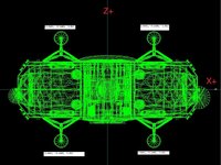
static const DWORD ntdvtx_geardown = 13;

static TOUCHDOWNVTX tdvtx_geardown[ntdvtx_geardown] = {

    {_V( 0   ,-2.57,10   ), 1e6, 1e5, 1.6, 0.1},

    {_V(-3.5 ,-2.57,-1   ), 1e6, 1e5, 3.0, 0.2},

    {_V( 3.5 ,-2.57,-1   ), 1e6, 1e5, 3.0, 0.2},

    {_V(-8.5 ,-0.3 ,-7.05), 1e7, 1e5, 3.0},

    {_V( 8.5 ,-0.3 ,-7.05), 1e7, 1e5, 3.0},

    {_V(-8.5 ,-0.4 ,-3   ), 1e7, 1e5, 3.0},

    {_V( 8.5 ,-0.4 ,-3   ), 1e7, 1e5, 3.0},

    {_V(-8.85, 2.3 ,-5.05), 1e7, 1e5, 3.0},

    {_V( 8.85, 2.3 ,-5.05), 1e7, 1e5, 3.0},

    {_V(-8.85, 2.3 ,-7.05), 1e7, 1e5, 3.0},

    {_V( 8.85, 2.3 ,-7.05), 1e7, 1e5, 3.0},

    {_V( 0   , 2   , 6.2 ), 1e7, 1e5, 3.0},

    {_V( 0   ,-0.6 ,10.65), 1e7, 1e5, 3.0}

};


static const DWORD ntdvtx_gearup = 13;

static TOUCHDOWNVTX tdvtx_gearup[ntdvtx_gearup] = {

    {_V( 0   ,-1.5 ,9),     1e7, 1e5, 3.0, 3.0},

    {_V(-6   ,-0.8 ,-5),    1e7, 1e5, 3.0, 3.0},

    {_V( 3   ,-1.2 ,-5),    1e7, 1e5, 3.0, 3.0},

    {_V(-8.5 ,-0.3 ,-7.05), 1e7, 1e5, 3.0},

    {_V( 8.5 ,-0.3 ,-7.05), 1e7, 1e5, 3.0},

    {_V(-8.5 ,-0.4 ,-3   ), 1e7, 1e5, 3.0},

    {_V( 8.5 ,-0.4 ,-3   ), 1e7, 1e5, 3.0},

    {_V(-8.85, 2.3 ,-5.05), 1e7, 1e5, 3.0},

    {_V( 8.85, 2.3 ,-5.05), 1e7, 1e5, 3.0},

    {_V(-8.85, 2.3 ,-7.05), 1e7, 1e5, 3.0},

    {_V( 8.85, 2.3 ,-7.05), 1e7, 1e5, 3.0},

    {_V( 0   , 2   , 6.2 ), 1e7, 1e5, 3.0},

    {_V( 0   ,-0.6 ,10.65), 1e7, 1e5, 3.0}

};


// ==============================================================

// Overloaded callback functions

// ==============================================================


// --------------------------------------------------------------

// Set vessel class parameters

// --------------------------------------------------------------


...


SetTouchdownPoints (tdvtx_geardown, ntdvtx_geardown);

...

void DeltaGlider::SetGearParameters (double state)
{
    if (state == 1.0) {
        if (!bGearIsDown) {
            SetTouchdownPoints (tdvtx_geardown, ntdvtx_geardown);
            SetNosewheelSteering (true);
            bGearIsDown = true;
        }
    } else {
        if (bGearIsDown) {
            SetTouchdownPoints (tdvtx_gearup, ntdvtx_gearup);
            SetNosewheelSteering (false);
            bGearIsDown = false;
        }
    }
}

What would be super-cool would be a way to make a collision mesh in say Blender, then have an export script that translates it into a static TOUCHDOWNVTX format. It is certainly possible. A Blender export script would do it with ease.
 
Last edited:
Confused. I thought I followed the example of the Delta glider. The DG has 3 landing gear points. While my Alpaca and LM have 4.

But I guess the question is: can orbiter look at each TD point and adjust the vessel accorded to the terrain.
 
Confused. I thought I followed the example of the Delta glider. The DG has 3 landing gear points. While my Alpaca and LM have 4.

But I guess the question is: can orbiter look at each TD point and adjust the vessel accorded to the terrain.

Yes, it does ! Those points define a real 3D collision mesh computed against the terrain. The 3 first ones define the triangle on which the mesh is supposed to rest "by default", that's all.

Given that your lander is pretty much a shoebox with 4 legs, I'd first define the 4 points that are the feet of those legs (the 3 first ones will be the "default triangle"), then the 8 points that would define the "shoebox" itself. Get the vertex coordinates from Anim8tor, and don't forget the left-handed conversion. You should end with 12 points.

And now if for some reason the lander ends on the roof, the physics will still be quite in sync with the mesh. Also like in the DG example you can define an alternate collision mesh in the case where the landing gear is retracted (or broken...)
 
@gattispilot can post the your code of the call to SetTouchdownPoints? It has not even occured to me that you might be using the wrong one, but I guess it's a possibility.
 
// values from Delta Glider // point, stiffness, dampening, isotropic/lateral friction coefficient, longitudinal friction coefficient (only used for first 3 points) const double pesototal=LEM_AscentMASS+LEM_DescentMASS+LEM_DescentFUEL+LEM_AscentFUEL; const double xtx_target=-0.1; const double xtst=(-1)*(pesototal*9.80655)/(3*xtx_target); const double xtda=0.9*(2*sqrt(pesototal*xtst)); static const DWORD ntdvtx_geardown = 12; static TOUCHDOWNVTX tdvtx_geardown[ntdvtx_geardown] = { {_V(3.4641, -4.1609, 3.452), 70007.4, 49275.1, 3, .2},//RIGHTUP LG { _V(-3.4641, -4.1609, 3.452), 70007.4, 49275.1, 3, .2},//LEFTUP LG {_V(-3.4641, -4.1609, -3.452), 70007.4, 49275.1, 3, .2},//LEFTDOWN LG { _V(3.4641, -4.1609, -3.452), 70007.4, 49275.1, 3, .2},//RIGHTDOWN LG {_V(6, -2.5, 2), 70007.4, 49275.1, .1, .2},//BTTOM RIGHT {_V(-6, -2.5, 2), 70007.4, 49275.1, .1, .2},//BTTOM RIGHT {_V(-6, -2.5, -2), 70007.4, 49275.1, .1, .2},//BTTOM RIGHT {_V(6, -2.5, -2), 70007.4, 49275.1, .1, .2},//BTTOM RIGHT {_V(6, 2, 2), 70007.4, 49275.1, .1, .2},//TOP RIGHT {_V(-6, 2, 2), 70007.4, 49275.1, .1, .2},//TOP RIGHT {_V(-6, 2, -2), 70007.4, 49275.1, .1, .2},//TOP RIGHT {_V(6, 2, -2), 70007.4, 49275.1, .1, .2},//TOP RIGHT }; AND CALLED HERE:
void SpiderLEM::clbkSetClassCaps (FILEHANDLE cfg) { // Define default physical parameters SetSize(6); // Set default size SetCrossSections(LEM_CS); // Set physical (x,y,z) cross sections SetPMI(LEM_PMI); // Set principal moments of inertia SetRotDrag(LEM_RD); // Set rotational drag coefficients SetEmptyMass(5800); // Set starting mass SetDockParams(LEM_DockPOS, LEM_DockDIR, LEM_DockROT); // Define docking port //SetTouchdownPoints (LEM_DescentTDP[0]+LEM_DescentOFFSET, LEM_DescentTDP[1]+LEM_DescentOFFSET, LEM_DescentTDP[2]+LEM_DescentOFFSET); // Set touchdown points SetTouchdownPoints(tdvtx_geardown, ntdvtx_geardown); SetSurfaceFrictionCoeff(50, 50);
 

Attachments

  • ALPACATD5.jpg
    ALPACATD5.jpg
    48.1 KB · Views: 1
Back
Top