Orbit DAP

DaveS

Addon Developer
Addon Developer
Donator
Beta Tester
Joined
Feb 4, 2008
Messages
9,753
Reaction score
1,024
Points
203
I just wondered how operate the DAP, especially MM201.

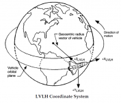
For example, I want it to hold a specific LVLH attitude but with DAP set to AUTO. So how do I command it to do that?

Let's say that the LVLH attitude I want has the following attitude angles:

P:0
Y:-90
R:180

How do I make it track that LVLH attitude? And how do I change the TARGET ID item on MM201?
 
At the moment TARGET ID 2 is the only value used by SSU. I haven't coded the DAP to point at other targets.
 
At the moment TARGET ID 2 is the only value used by SSU. I haven't coded the DAP to point at other targets.
OK, what about the other question?
 
The DAP works by pointing a vector towards the target object (at the moment, the Earth is the only valid target).

To track a specific LVLH attitude, you need to set the BODY VECT item to 5. The P, Y and OM angles are used to define the target vector. The P and Y angles define the (Euler) angles between the body vector and the shuttle's +X axis (the +Z axis in Orbiter). The OM angles specifies a rotation of the shuttle around the body vector.

For the attitude
P:0
Y:-90
R:180
the body vector needs to be perpendicular to the shuttle's wings, so the P and Y angles are 90 and 0. To get the 90 degree yaw angle, the OM angle needs to be either 90 or 270 degrees, depending on the direction in which the shuttle needs to yaw.
 
OK. So P is attitude around the shuttle's X-axis and Y is attitude around the shuttle's Z-axis and OM is attitude around the shuttle's Y-axis?

After some trial and error I have managed to place specific data to some common attitudes:

-ZLV +XVV(tail in VV, PLB face nadir):
P: 90
Y: 0
OM: 0

-ZLV +YVV(stbd wing in VV, PLB face nadir):
P: 0
Y: 90
OM: 90

+ZLV +XVV(nose in VV, PLB face zenith):
P: 270
Y: 0
OM: 0
 
OK. So P is attitude around the shuttle's X-axis and Y is attitude around the shuttle's Z-axis and OM is attitude around the shuttle's Y-axis?
It's a bit more complicated than that. The P, Y and OM angles are Euler angles, and not just angles between the body vector and the reference frame.

Think of Orbiter's reference frame, with the +Z axis through the shuttle's nose. The P value rotates the entire frame around the X axis. The Y value represents a rotation around the Y axis of the frame (performed after the P rotation). OM is a rotation around the Z axis. Once all rotations are performed, the +Z axis will be the body vector.
 
Is there a checklist for flying a Hubble approach ? Seems the shuttle flies LVLH while tracking the hubble then switches to inertial to capture, but hubble has to be oriented in the correct angle for that. How would you do that with SSU ?
 
Is there a checklist for flying a Hubble approach ? Seems the shuttle flies LVLH while tracking the hubble then switches to inertial to capture, but hubble has to be oriented in the correct angle for that. How would you do that with SSU ?

Pretty much like approaching the ISS, I would say.

I still wait for the STS-125 checklists to appear on the FOIA page.
 
What would I enter into the DAP to fly bay to the Earth, tail first ?
 
Worked like a charm ! Do you next press LVLH on the DAP to hold it there ?
 
In this case, either AUTO or LVLH will work, although in real life the DAP would remain in AUTO. AUTO holds the shuttle in the attitude set using UNIV PTG (ITEM 18/19). LVLH will hold the shuttle in the current LVLH attitude. In this case, the autopilot is already set up to maintain a LVLH attitude, so there's no point in setting the DAP to AUTO.
 
This is still a little confusing...

Looking at CRT MFD's doc, it mentions setting a yaw of 270 (as an example), yet I was not able to enter 270. It showed up in the text stream in the lower left hand corner of my computer monitor (the information stream), but in the MFD, nothing changed. However, I can enter positive or negative 90.

Also, reading that document gave the impression that +X, BV=1, would point it nose first (prograde). And that BV=2 would be tail first (retrograde), and that BV=3 would be top-side first (either normal or anti-normal).

When I entred ITEM 19 EXEC with BV=1, it pointed me straight down, -90* pitch at the planet.

In this thread it was said that the shuttles X axis is different from Orbiter's X axis (which only further confuses the issue) (as does ITEM 19 in MM202 being +(delta)VX, seems like +X is forward).

Is there a more straight forward way of explaining this? And in addition to that, what would be req'd for the 4 standard facings (Prograde, Retrograde, Orbit Normal, and Orbit Anti-Normal)? It looks like there was an attempt to list some of those things, but the nomenclature used didn't help much. (nor does being 3am right now help, but hey! lol )

Additionally, if I wanted to do an alignment burn (yes, I know that isn't usually done, but suppose I'm not running a historical scenario, or just messed up somewhere), would I be able to use MM202 for that? I recall reading here that there is no throttle button or lever in the pit for the OMS engines, that they are controlled via GPC only, so to do this, I would have to configure an OMS burn through CRT MFD MM202. But, would I simply use ITEM 20? If so, which would be 'normal' (+Y or -Y) and which would be anti-normal? Or would it be ITEM 21 instead? And if so, which is which (+ or -Z being normal or anti-normal)?
 
This is still a little confusing...

Looking at CRT MFD's doc, it mentions setting a yaw of 270 (as an example), yet I was not able to enter 270. It showed up in the text stream in the lower left hand corner of my computer monitor (the information stream), but in the MFD, nothing changed. However, I can enter positive or negative 90.

Also, reading that document gave the impression that +X, BV=1, would point it nose first (prograde). And that BV=2 would be tail first (retrograde), and that BV=3 would be top-side first (either normal or anti-normal).

When I entred ITEM 19 EXEC with BV=1, it pointed me straight down, -90* pitch at the planet.

In this thread it was said that the shuttles X axis is different from Orbiter's X axis (which only further confuses the issue) (as does ITEM 19 in MM202 being +(delta)VX, seems like +X is forward).

Is there a more straight forward way of explaining this? And in addition to that, what would be req'd for the 4 standard facings (Prograde, Retrograde, Orbit Normal, and Orbit Anti-Normal)? It looks like there was an attempt to list some of those things, but the nomenclature used didn't help much. (nor does being 3am right now help, but hey! lol )
The way the DAP works is this: the settings in MM201 define an axis which is pointed at the Earth. Selecting BV=1 defines the axis as the shuttle's +X axis, so this points the nose at the Earth. Once the axis is pointed at the Earth, the OM value defines how much the shuttle is rotated around the axis defined by the P and Y values. I've attached a picture from the SCOM showing how the shuttle body axes are defined.

Prograde: P 90, Y 0, OM 0
Retrograde: P180, Y 0, OM 0 or P90, Y 0, OM 180
Normal/Anti-Normal: P 90, Y 0, OM 90/270

Additionally, if I wanted to do an alignment burn (yes, I know that isn't usually done, but suppose I'm not running a historical scenario, or just messed up somewhere), would I be able to use MM202 for that? I recall reading here that there is no throttle button or lever in the pit for the OMS engines, that they are controlled via GPC only, so to do this, I would have to configure an OMS burn through CRT MFD MM202. But, would I simply use ITEM 20? If so, which would be 'normal' (+Y or -Y) and which would be anti-normal? Or would it be ITEM 21 instead? And if so, which is which (+ or -Z being normal or anti-normal)?
You can still control the OMS engines manually, without using CRT MFD; all you need to do is arm the engines, and then you can use the + button to fire them.
 

Attachments

  • body axes.PNG
    body axes.PNG
    59.6 KB · Views: 786
Thanks, that makes more sense now.


You can still control the OMS engines manually, without using CRT MFD; all you need to do is arm the engines, and then you can use the + button to fire them.

Well, yes, but suppose I wanted to use CRT MFD to do it. Is it possible? (additionally, I read that there was a plan to remove that manual cheat in future versions as more stuff is detailed, but really I just like using CRT MFD :) )
 
You can use dV in the Y axis (ITEM 20) to change planes; I think normal is in the -Y direction. Drawing of LVLH axies is attached below.
 

Attachments

  • LVLH axes.PNG
    LVLH axes.PNG
    92.2 KB · Views: 703
Back
Top