So I have been trying to explore the boundaries of the physical modeling capabilities in Orbiter, not just for orbital dynamics and aerodynamics, but contact forces and buoyancy, in water as well as in the atmosphere.
After some explorations of the "new" touchdown model with my Zorb addon, I realized that it might be possible to model buoyancy for a vessel at the surface by relating the stiffness in the touchdown model to the hydrostatic equation which describes the pressure distribution on a semi-submerged vessel.
The Touchdown Model
The touchdown model applies a simple forced mass-spring-damper model to each of the contact points:[math]my'' + cy' + ky = \sum F_y[/math]
where m is the mass supported by the contact, y is the displacement, y' is the rate of displacement, and y'' is the acceleration. The coefficients are defined as:
Stiffness coefficient (Applied spring force per unit displacement): [math]k = F_S/y[/math]
Damping coefficient (Applied damping force per unit rate of displacement): [math]c = F_D/y'[/math]
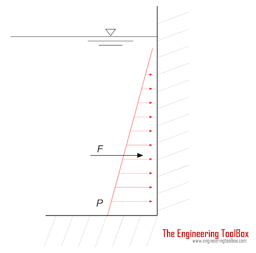
So if you have a vessel with n contact points all at y = 0 (where y is in the local vertical direction opposite gravity), and you specify a vessel weight mg and a stiffness k, the mesh will "sink" until the weight is supported by the springs at a depth y = mg/nk, which looks something like this:

Note that there are dampers in parallel with the springs to dissipate energy, but I've omitted them for clarity to focus on the spring forces. The dampers only oppose motion and don't apply forces in static situations.
The Hydrostatic Equation
The hydrostatic equation describes the increase in pressure in a fluid as depth increases. The pressure force at a given depth has to be equal to the weight of the fluid above it. If you visualize a vertical column of fluid with height y (again, in the direction of the local gravitational acceleration), and the column has a cross sectional area A, the increase in pressure [imath]\Delta P[/imath] at the bottom of the column relative to the top required to support the weight of the fluid is given by:
Relating the Hydrostatic Pressure and Touchdown Stiffness
Touchdown forces only act in the local y direction, where hydrostatic forces can generally act in any direction depending on the orientation of a hull surface. However, if we use a simple rectangular solid as a vessel with the submerged surfaces parallel with the planet surface (similar to the schematic above), we can implement an accurate flotation model in Orbiter as it exists now. Assuming a simple 1 m cube with vertices on each corner, and we want it to float at the surface, so only the bottom four vertices are submerged. So the weight of the vessel is supported by n=4 springs, and that weight must be equal to the hydrostatic pressure force on the vessel:
For this to be true for the vessel to float at the surface, the density of the vessel cannot exceed the density of water ([imath]\rho[/imath] = 1000 kg/m3 for fresh water, somewhat higher for sea water).
So we can determine the necessary spring stiffness for the contact model by:
[math] mg = \rho g y A = n k y[/math]
[math] k = \rho g A / n[/math]
A / n describes the area associated with each vertex and the area upon which the local hydrostatic force acts.
Testing
So I coded a simple vessel with a 1 m cube as described above, and made a little add-on (attached). It has a magical massless thruster that allows it to leave the Landed state and be supported on the contact points, and to let users "poke" it to see it bob around. The mass was set to 500 kg, 50% the density of water. This cube should float halfway out of the surface when supported by its contact points if they mimic the hydrostatic forces correctly. In this case n = 4, and A = 1 m2.
At the start of the scenario the mesh is "Landed" at KSC (it's on the runway, any planet surface will work as we can't distinguish water from rock at the moment). It is hovering above the surface:

The mesh has a simple gradation texture measuring the 1 meter vertical dimension so we can visually see the depth to which it sinks. When we hit the throttle (thrust is in -Y direction and about 20% of the vessel mass), the vessel falls into the surface, bobs around a bit, and then stabilizes...at 0.5 m, as expected:

The selection of damping constant is more artistic. If the damping value is set to 0, this cube will bob up and down forever. If a small amount of damping is applied it will bob up and down a bit before coming to rest in a pleasantly realistic manner. A small fraction of the critical damping value for this system is used.
Initial Conclusions
So based on this, in Orbiter we currently can model reasonably accurate net buoyant forces on semi-submerged objects, so long as submerged surfaces are parallel to the planet surface.
In order to generalize this to more interesting hull shapes, two things would need to be accessible from Orbiter.
After some explorations of the "new" touchdown model with my Zorb addon, I realized that it might be possible to model buoyancy for a vessel at the surface by relating the stiffness in the touchdown model to the hydrostatic equation which describes the pressure distribution on a semi-submerged vessel.
The Touchdown Model
The touchdown model applies a simple forced mass-spring-damper model to each of the contact points:[math]my'' + cy' + ky = \sum F_y[/math]
where m is the mass supported by the contact, y is the displacement, y' is the rate of displacement, and y'' is the acceleration. The coefficients are defined as:
Stiffness coefficient (Applied spring force per unit displacement): [math]k = F_S/y[/math]
Damping coefficient (Applied damping force per unit rate of displacement): [math]c = F_D/y'[/math]
So if you have a vessel with n contact points all at y = 0 (where y is in the local vertical direction opposite gravity), and you specify a vessel weight mg and a stiffness k, the mesh will "sink" until the weight is supported by the springs at a depth y = mg/nk, which looks something like this:
Note that there are dampers in parallel with the springs to dissipate energy, but I've omitted them for clarity to focus on the spring forces. The dampers only oppose motion and don't apply forces in static situations.
The Hydrostatic Equation
The hydrostatic equation describes the increase in pressure in a fluid as depth increases. The pressure force at a given depth has to be equal to the weight of the fluid above it. If you visualize a vertical column of fluid with height y (again, in the direction of the local gravitational acceleration), and the column has a cross sectional area A, the increase in pressure [imath]\Delta P[/imath] at the bottom of the column relative to the top required to support the weight of the fluid is given by:
Pressure Force = Weight
[math]\Delta P A = \rho g y A[/math]
[math]\Delta P = \rho g y[/math]
The hydrostatic pressure for a given fluid is only a function of depth y. This pressure will apply a normal pressure force to any solid surface at that depth, regardless of the orientation of that surface.[math]\Delta P A = \rho g y A[/math]
[math]\Delta P = \rho g y[/math]
Relating the Hydrostatic Pressure and Touchdown Stiffness
Touchdown forces only act in the local y direction, where hydrostatic forces can generally act in any direction depending on the orientation of a hull surface. However, if we use a simple rectangular solid as a vessel with the submerged surfaces parallel with the planet surface (similar to the schematic above), we can implement an accurate flotation model in Orbiter as it exists now. Assuming a simple 1 m cube with vertices on each corner, and we want it to float at the surface, so only the bottom four vertices are submerged. So the weight of the vessel is supported by n=4 springs, and that weight must be equal to the hydrostatic pressure force on the vessel:
Weight = Hydrostatic Force = Sum of Spring Forces
For this to be true for the vessel to float at the surface, the density of the vessel cannot exceed the density of water ([imath]\rho[/imath] = 1000 kg/m3 for fresh water, somewhat higher for sea water).
So we can determine the necessary spring stiffness for the contact model by:
[math] mg = \rho g y A = n k y[/math]
[math] k = \rho g A / n[/math]
A / n describes the area associated with each vertex and the area upon which the local hydrostatic force acts.
Testing
So I coded a simple vessel with a 1 m cube as described above, and made a little add-on (attached). It has a magical massless thruster that allows it to leave the Landed state and be supported on the contact points, and to let users "poke" it to see it bob around. The mass was set to 500 kg, 50% the density of water. This cube should float halfway out of the surface when supported by its contact points if they mimic the hydrostatic forces correctly. In this case n = 4, and A = 1 m2.
At the start of the scenario the mesh is "Landed" at KSC (it's on the runway, any planet surface will work as we can't distinguish water from rock at the moment). It is hovering above the surface:
The mesh has a simple gradation texture measuring the 1 meter vertical dimension so we can visually see the depth to which it sinks. When we hit the throttle (thrust is in -Y direction and about 20% of the vessel mass), the vessel falls into the surface, bobs around a bit, and then stabilizes...at 0.5 m, as expected:
The selection of damping constant is more artistic. If the damping value is set to 0, this cube will bob up and down forever. If a small amount of damping is applied it will bob up and down a bit before coming to rest in a pleasantly realistic manner. A small fraction of the critical damping value for this system is used.
Initial Conclusions
So based on this, in Orbiter we currently can model reasonably accurate net buoyant forces on semi-submerged objects, so long as submerged surfaces are parallel to the planet surface.
In order to generalize this to more interesting hull shapes, two things would need to be accessible from Orbiter.
- The depth to each submerged vertex of the mesh with a corresponding touchdown point definition. This allows the magnitude of the hydrostatic force to be calculated. An area would also need to be associated to each vertex for this calculation.
- The mean normal vector from the surface at each vertex. The total hydrostatic force acts normal to the submerged surface, but only the y-component of that force vector helps support the weight of the vessel. Hydrostatic forces in the X- and Z- directions can be integrated, but they should be equal and opposite. It may be possible to use the mesh outward normals for this IF they are applied correctly.
Attachments
Last edited:


")


