Is there a reason why the normal SRBs have 5 meshes (aft, aft_center, fwd_center, fwd and fwd_skirt), but there are only 4 FWC meshes (no fwd_skirt mesh)? IIRC, they both had 4 segments.

You are using an out of date browser. It may not display this or other websites correctly.
You should upgrade or use an alternative browser.
You should upgrade or use an alternative browser.
SSU Space Launch Complex 6 development
- Thread starter DaveS
- Start date
- Joined
- Feb 4, 2008
- Messages
- 9,761
- Reaction score
- 1,030
- Points
- 203
The plan was to use standard fwd skirts on the FWC SRBs.Is there a reason why the normal SRBs have 5 meshes (aft, aft_center, fwd_center, fwd and fwd_skirt), but there are only 4 FWC meshes (no fwd_skirt mesh)? IIRC, they both had 4 segments.
Do you have more detailed ISP information? I need vacuum and sea-level ISP, instead of just average ISP.Based on my research, it's the FWC SRMs. The nozzles and forward/aft skirts are dummy mock-ups although at least the forward/aft skirts used to be real until NASA requested them back to be used in the operational rotation of SRB components at KSC.
---------- Post added at 02:42 AM ---------- Previous post was at 02:31 AM ----------
Here's the numbers:
Propellant loading: 1,105,486 lbm
Empty mass: 117,074 lbm
Action time Impulse (lbf-sec): 297.53 x 10⁶
Action time ISP (lbf-sec/lbm): 267.53
Action time (sec): 121.28
Burn time (sec): 110.93
Burn time, average vacuum thrust (lbf): 2,617,000
Action time, average vacuum thrust (lbf): 2,453,000
MOP (psia): 927.8
MOF (lbf): 3,329,000
Burn rate (ips): 0.369
Average nozzle expansion ratio: 7.48
I'll get on the meshes.
- Joined
- Feb 4, 2008
- Messages
- 9,761
- Reaction score
- 1,030
- Points
- 203
Nope, sorry. That's the only information in the document. Just a note that the data is for vacuum and 60°F.Do you have more detailed ISP information? I need vacuum and sea-level ISP, instead of just average ISP.
One other thing I've noticed is that the thrust of the FWC SRBs is much less than the thrust of the normal SRBs (15.13 MN vs. 14.81 MN), so the normal SRBs actually perform better than the FWC SRBs. This means that either the data for the regular SRBs is wrong, or the FWC SRBs have a different thrust profile. Do you have a link to the document you're getting the FWC data from?
- Joined
- Feb 4, 2008
- Messages
- 9,761
- Reaction score
- 1,030
- Points
- 203
Here it is: http://dl.dropbox.com/u/24122088/Space Shuttle Filament Wound Case SRM Test Results.pdfOne other thing I've noticed is that the thrust of the FWC SRBs is much less than the thrust of the normal SRBs (15.13 MN vs. 14.81 MN), so the normal SRBs actually perform better than the FWC SRBs. This means that either the data for the regular SRBs is wrong, or the FWC SRBs have a different thrust profile. Do you have a link to the document you're getting the FWC data from?
---------- Post added at 06:36 AM ---------- Previous post was at 06:33 AM ----------
I think that there might be some incorrect scaling issues with the regular SRBs. I'll check it. The FWC SRMs should be longer (37.8345 m) than the regular SRBs (36.6375 m).I've checked in a preliminary version of the FWC code. Apart from the performance issues noted above, the FWC meshes don't seem to match the meshes for the normal casings. I've attached a screenshot of the FWC and normal meshes for comparison.
- Joined
- Feb 4, 2008
- Messages
- 9,761
- Reaction score
- 1,030
- Points
- 203
Just checked the original steel casing SRM segments and it at least the aft segment is off in length. Traced it to the actual motor case, the aft skirt and nozzle are fine. I'll check the other segments to see if any corrections are necessary.

- Joined
- Feb 4, 2008
- Messages
- 9,761
- Reaction score
- 1,030
- Points
- 203
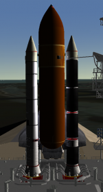
That's the actual flight configuration. Not sure why the b&w color configuration.Would the flight FWC SRMs been that colour, or would they have been painted white?
---------- Post added at 09:49 PM ---------- Previous post was at 09:47 PM ----------
With the FWC SRMs done, I think we got everything needed to make polar flights possible with SSU. Anyone notice anything critical missing?

- Joined
- Feb 6, 2008
- Messages
- 38,938
- Reaction score
- 3,937
- Points
- 203
- Location
- Wolfsburg
- Preferred Pronouns
- Sire
With the FWC SRMs done, I think we got everything needed to make polar flights possible with SSU. Anyone notice anything critical missing?
Aside of payloads for such a mission? do we have the abort sites?
Does the autopilot work well with polar missions or do we need new constants (polar = southern launch, could confuse the AP)
- Joined
- Feb 4, 2008
- Messages
- 9,761
- Reaction score
- 1,030
- Points
- 203
That's one of the things I would like test, along with performance.Aside of payloads for such a mission? do we have the abort sites?
Does the autopilot work well with polar missions or do we need new constants (polar = southern launch, could confuse the AP)
- Joined
- Feb 6, 2008
- Messages
- 38,938
- Reaction score
- 3,937
- Points
- 203
- Location
- Wolfsburg
- Preferred Pronouns
- Sire
That's one of the things I would like test, along with performance.
Also, we would need something annoying: New calculations for the deorbit burn and entry interface, since we have a different relative velocity of the atmosphere to the space shuttle.
I can do this soon. Do you have animation data for the SLC-6 meshes?
- Joined
- Feb 4, 2008
- Messages
- 9,761
- Reaction score
- 1,030
- Points
- 203
Should be fairly simple. All the structures except for the Access Tower translates on rails.I can do this soon. Do you have animation data for the SLC-6 meshes?
Here's the SC3 data on the Access Tower:
Code:
[CONFIG]
MESHNAME="VandenbergAFB\SLC-6_STS_AT"
FOCUS=1
SIZE=70
EMPTY_MASS=2000000
COG=0.01


[ANIM_SEQ_0]	;Intertank Access Arm
KEY=K
DURATION=210
INIT_POS=1 	;Initial position of animation in the mesh

[ANIM_SEQ_1]	;GOX Vent Arm
KEY=G
DURATION=45

[ANIM_SEQ_2]	;Crew Access Arm
KEY=S
DURATION=45


[ANIM_COMP_0]
SEQ=0
GROUPS=5
RANGE(0,1)
TYPE=ROTATE
ROT_PNT=(8.87,43.15,18.57)
ROT_AXIS=(0,1,0)
ANGLE=210

[ANIM_COMP_1]
SEQ=1
GROUPS=6,14,15,16,17,18,19,20,21,22,23
RANGE(0,1)
TYPE=ROTATE
ROT_PNT=(-2.03,58.99,14.87)
ROT_AXIS=(0,-1,0)
ANGLE=74.75

[ANIM_COMP_2]
SEQ=2
GROUPS=8
RANGE(0,1)
TYPE=TRANSLATE
SHIFT=(12.5,0,-2.2)
Another that I haven't animated is the structure on which the GH2 vent line and Intertank Access Arm is mounted. That should be a simple 90° rotation so that the MST can move into the correct stacking position over the launch mount.
---------- Post added at 08:10 AM ---------- Previous post was at 07:46 AM ----------
Another thing is the doors on the SAB: They move just like the ones on the VAB High Bays.
---------- Post added 12-03-11 at 12:31 AM ---------- Previous post was 12-02-11 at 08:10 AM ----------
Another thing: Would it be possible to add the water deluge sprays? Here's a few images showing the locations of the various nozzles on the Launch Mount:


---------- Post added at 12:34 AM ---------- Previous post was at 12:31 AM ----------
And here's the pivot point for the GH2 vent line/IAA structure: 6.25, 41.98, -0.90
- Joined
- Feb 4, 2008
- Messages
- 9,761
- Reaction score
- 1,030
- Points
- 203
Just about completed the new right SRB exhaust duct/pit. Once the new ducts/pits are done, I'll move on to add the pad lights and the ET Ice Suppression System (ISS) building and ducts. Then I'll add the cryo spheres and the "flower box" as well as the water treatment holding tank.

---------- Post added at 10:20 AM ---------- Previous post was at 09:46 AM ----------
Left SRB exhaust duct/pit done. Just the SSME exhaust duct/pit left.

---------- Post added at 02:52 PM ---------- Previous post was at 10:20 AM ----------
All he ducts/pits done as well as the ET ISS building/ducts and the "flower box".

---------- Post added at 10:48 PM ---------- Previous post was at 02:52 PM ----------
SiameseCat: How is the SLC-6 code work coming along?
---------- Post added 12-05-11 at 12:43 AM ---------- Previous post was 12-04-11 at 10:48 PM ----------
Here's the more or less completed work:

---------- Post added at 12:47 AM ---------- Previous post was at 12:43 AM ----------
New mesh and textures have been checked in. Looks good enough for now, just need to do some tweaking of the positions of the ET ISS pipes and some of the pad lights.
---------- Post added at 05:48 AM ---------- Previous post was at 12:47 AM ----------
The final mesh and texture in Orbiter which has now been checked in.

---------- Post added at 10:20 AM ---------- Previous post was at 09:46 AM ----------
Left SRB exhaust duct/pit done. Just the SSME exhaust duct/pit left.
---------- Post added at 02:52 PM ---------- Previous post was at 10:20 AM ----------
All he ducts/pits done as well as the ET ISS building/ducts and the "flower box".
---------- Post added at 10:48 PM ---------- Previous post was at 02:52 PM ----------
SiameseCat: How is the SLC-6 code work coming along?
---------- Post added 12-05-11 at 12:43 AM ---------- Previous post was 12-04-11 at 10:48 PM ----------
Here's the more or less completed work:
---------- Post added at 12:47 AM ---------- Previous post was at 12:43 AM ----------
New mesh and textures have been checked in. Looks good enough for now, just need to do some tweaking of the positions of the ET ISS pipes and some of the pad lights.
---------- Post added at 05:48 AM ---------- Previous post was at 12:47 AM ----------
The final mesh and texture in Orbiter which has now been checked in.
Can you post the scenario/base config files you used for that screenshot? It might be helpful for getting the coordinates for all the meshes.
- Joined
- Feb 4, 2008
- Messages
- 9,761
- Reaction score
- 1,030
- Points
- 203
Checked in the cfg files and the scenario.Can you post the scenario/base config files you used for that screenshot? It might be helpful for getting the coordinates for all the meshes.
Similar threads

- Replies
- 34
- Views
- 9K


- Replies
- 21
- Views
- 19K


- Replies
- 3
- Views
- 2K


- Replies
- 1
- Views
- 9K
